Basic commands (Measure distance)
Measure Distance 
It measures the distance between two objects. It allows to select points, faces, surfaces and solid bodies as object to measure the distance between. Other than points, the sw measures the minimum distance between the objects, calculating automatically the closest points.
Once pressed the button, the Distance panel appears:
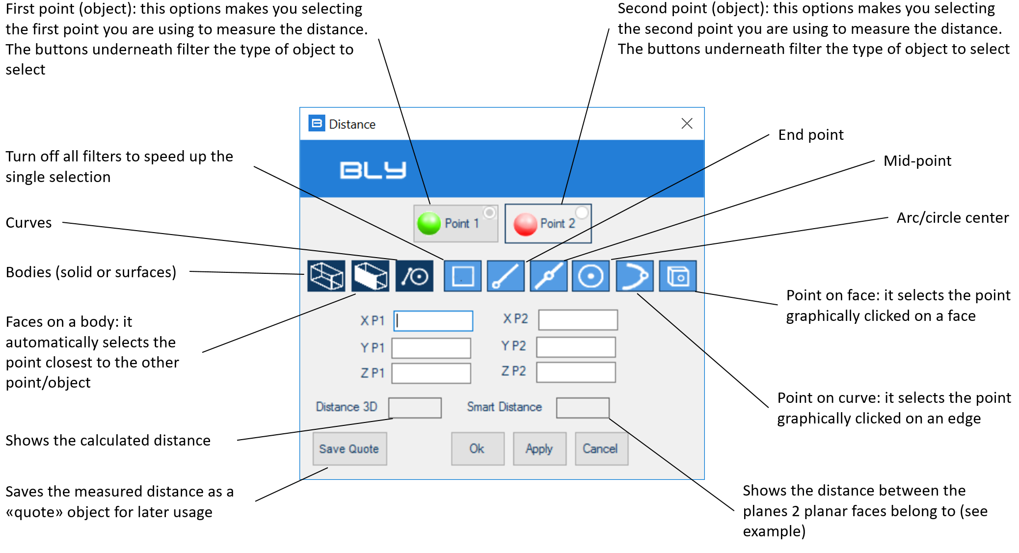
By default Bly asks you to select the Point 1 (greeen dot) first, but you can decide freely which object to select by pressing the objects' buttons.
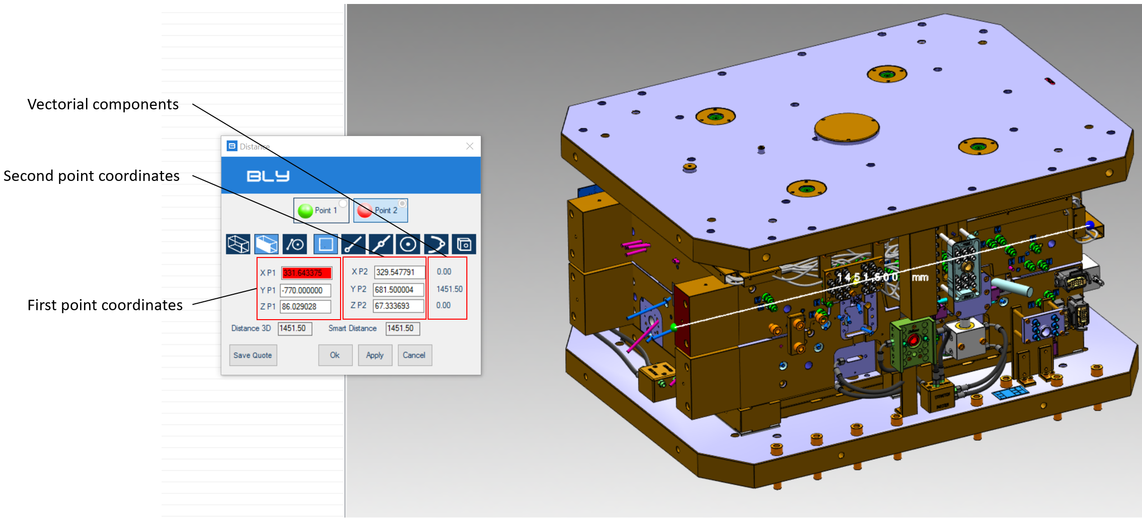
Once the two objects are selected, the window will show the coordinates of the selected objects, the measured distance and its vectorial elements in X,Y, and Z axis.
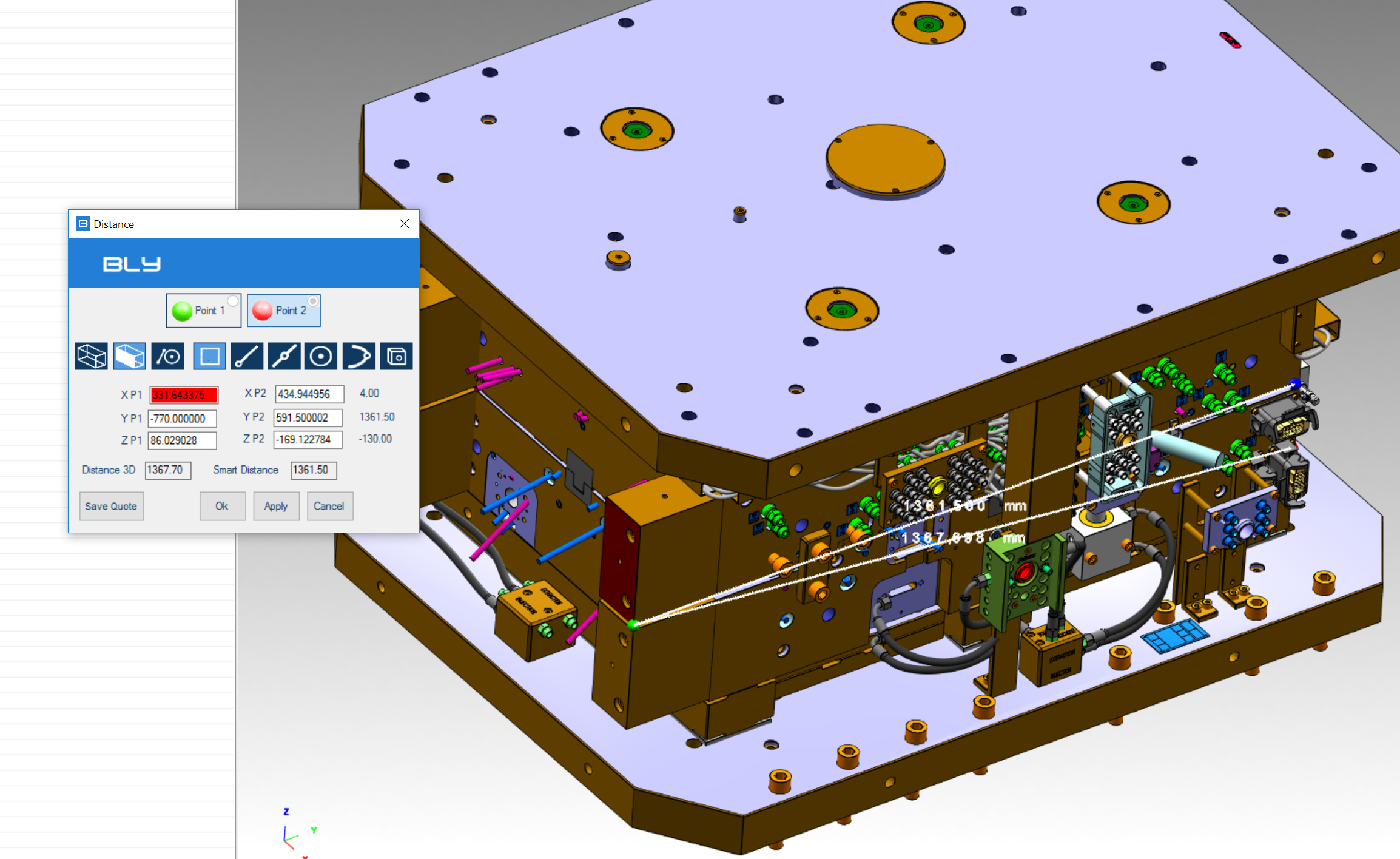
In case of parallel planar objects, Bly calculates both the real minimum distance and the theoretical projected shorter distance, called Smart Distance (see example below)
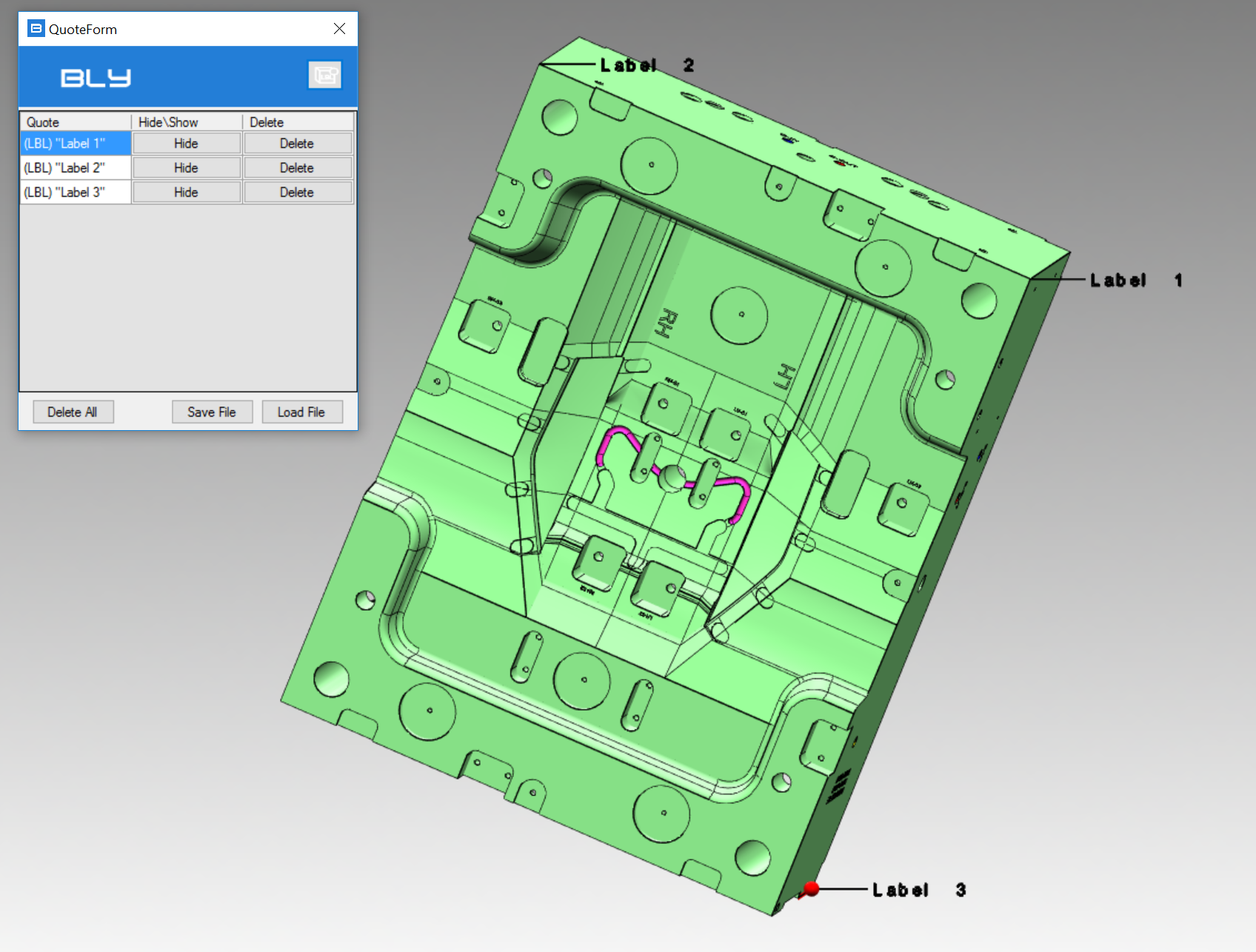
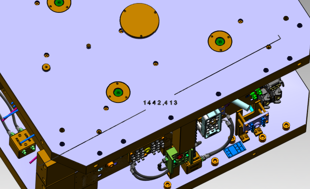
Save Quote button creates an object that remains visible after Mesuring Distance is closed and can be managed using Quote Form ![]() command (see later in this chapter)
command (see later in this chapter)
Measure Angle 
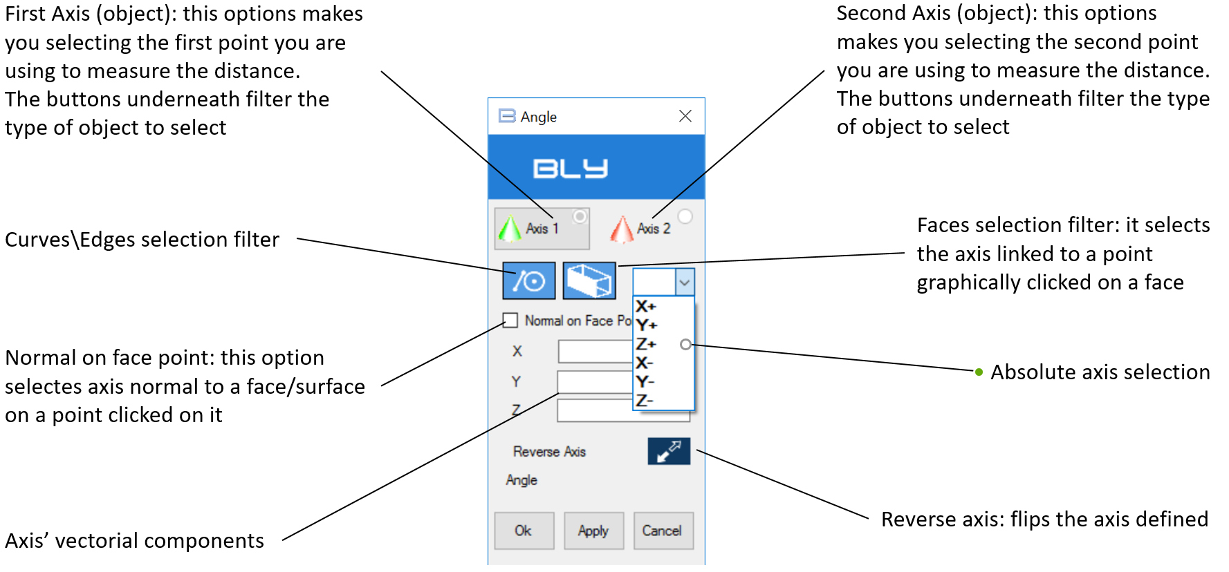
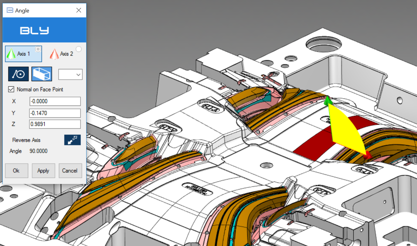
The command measures the angle between 2 axis. Axis can be defined using straight edges or vector associated to point onto faces or surfaces. Pressing the button will show the Angle window:
By default Bly asks you to select the Axis 1 (greeen arrow) first, but you can decide freely which object to select by pressing the objects' buttons.
Point Information 
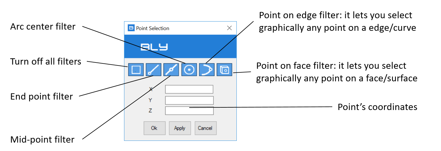
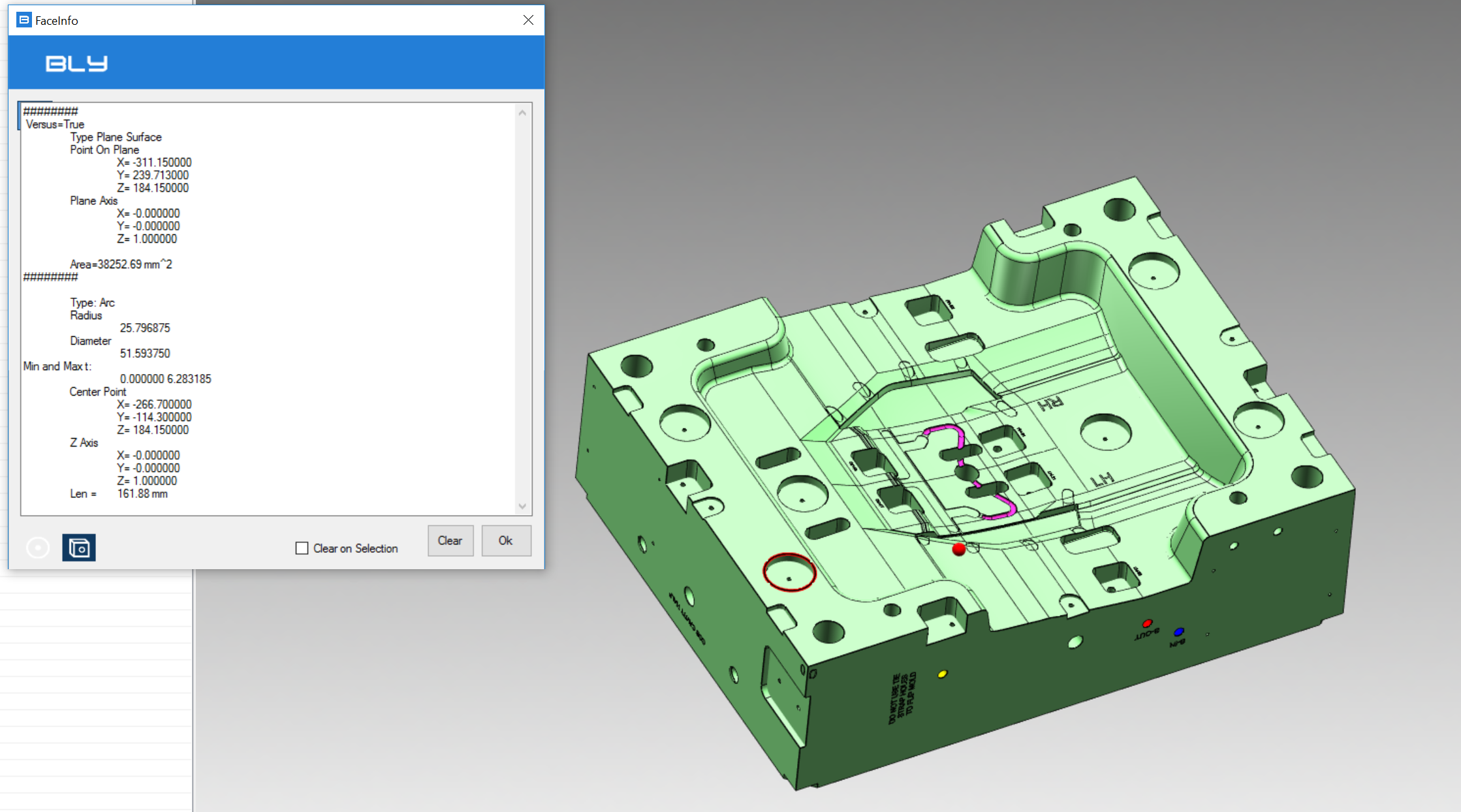
Choose this option if you want to get coordinates of a point on the model. After clicking on it, a Point Selection window will be displayed.
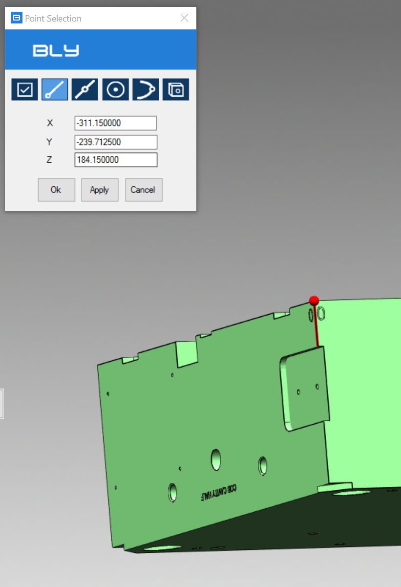
Here below an example of point selected:
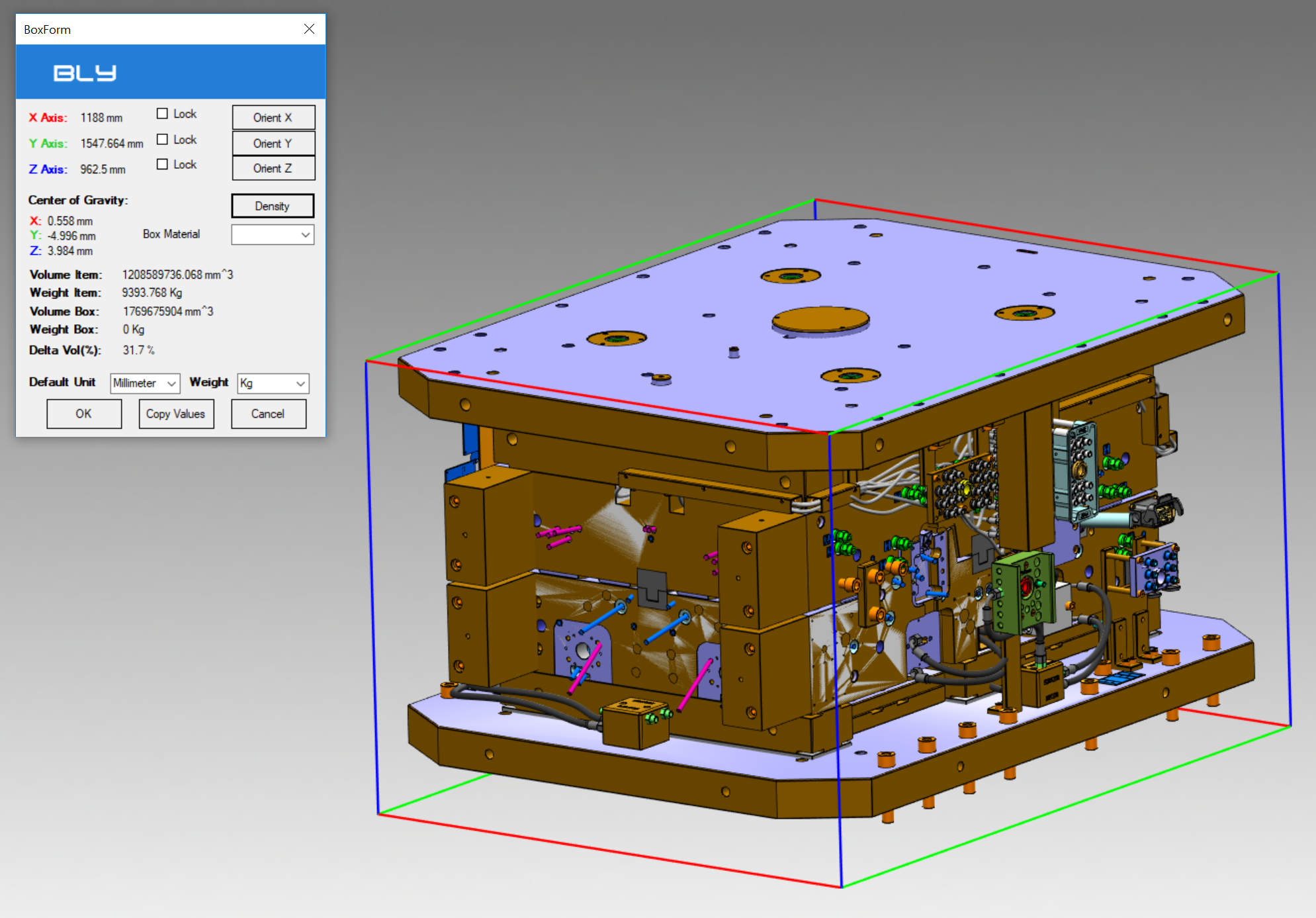
Show Bounding Box 
Bly calculates for each model and assemby its Bounding Box, which is defined as the smallest parallelepiped including the model. Show Bounding Box shows the bounding box of the displayed assembly.
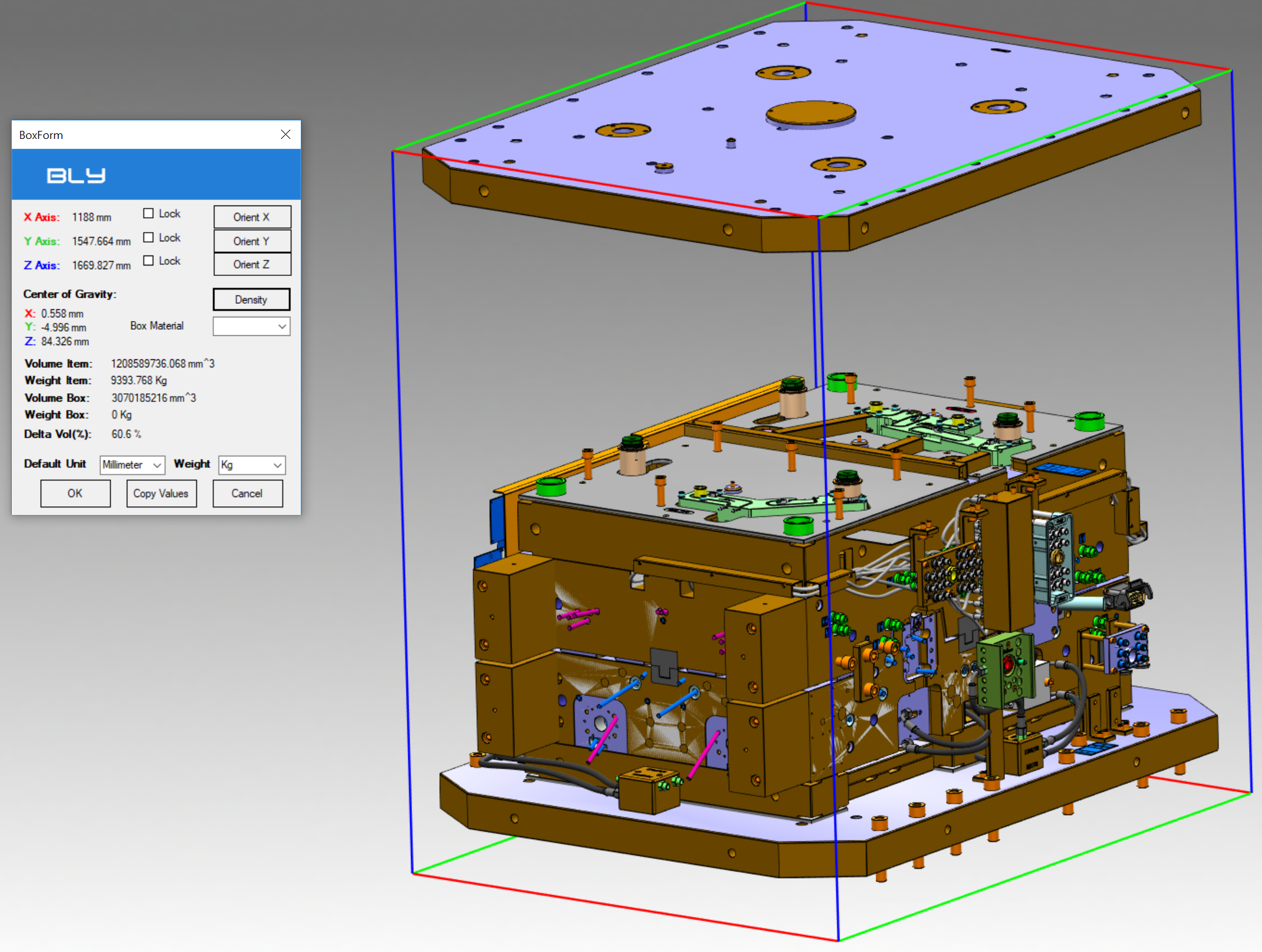
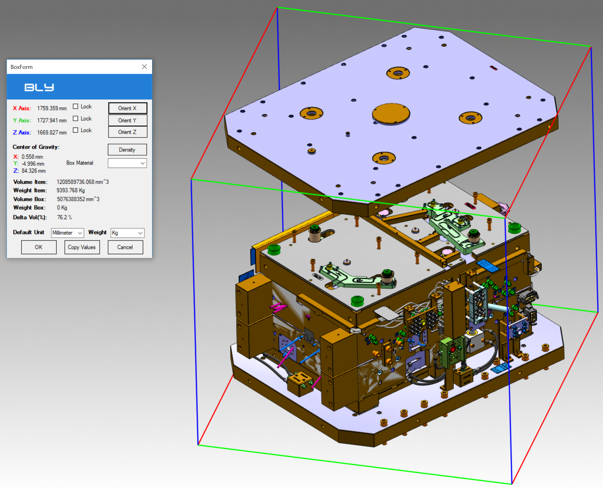
The bounding box is calculated on the actual assembly configuration, i.e. considering the component moved from the original position (see below).
It is possible to orient the box using Orient X, Orient Y or Orient Z buttons:
Copy Values
This button copies bounding box' dimensions and mass properties to clipboard. The values can then be pasted into an Excel or text file for further usage.
See more details and an example on this video
Curvature Analysis 
Curvature Analisys is a functionality aloowing to measure two properties of a face/surface: curvature and normal deviation from the absolute Z+ axis.
Curvature measurement
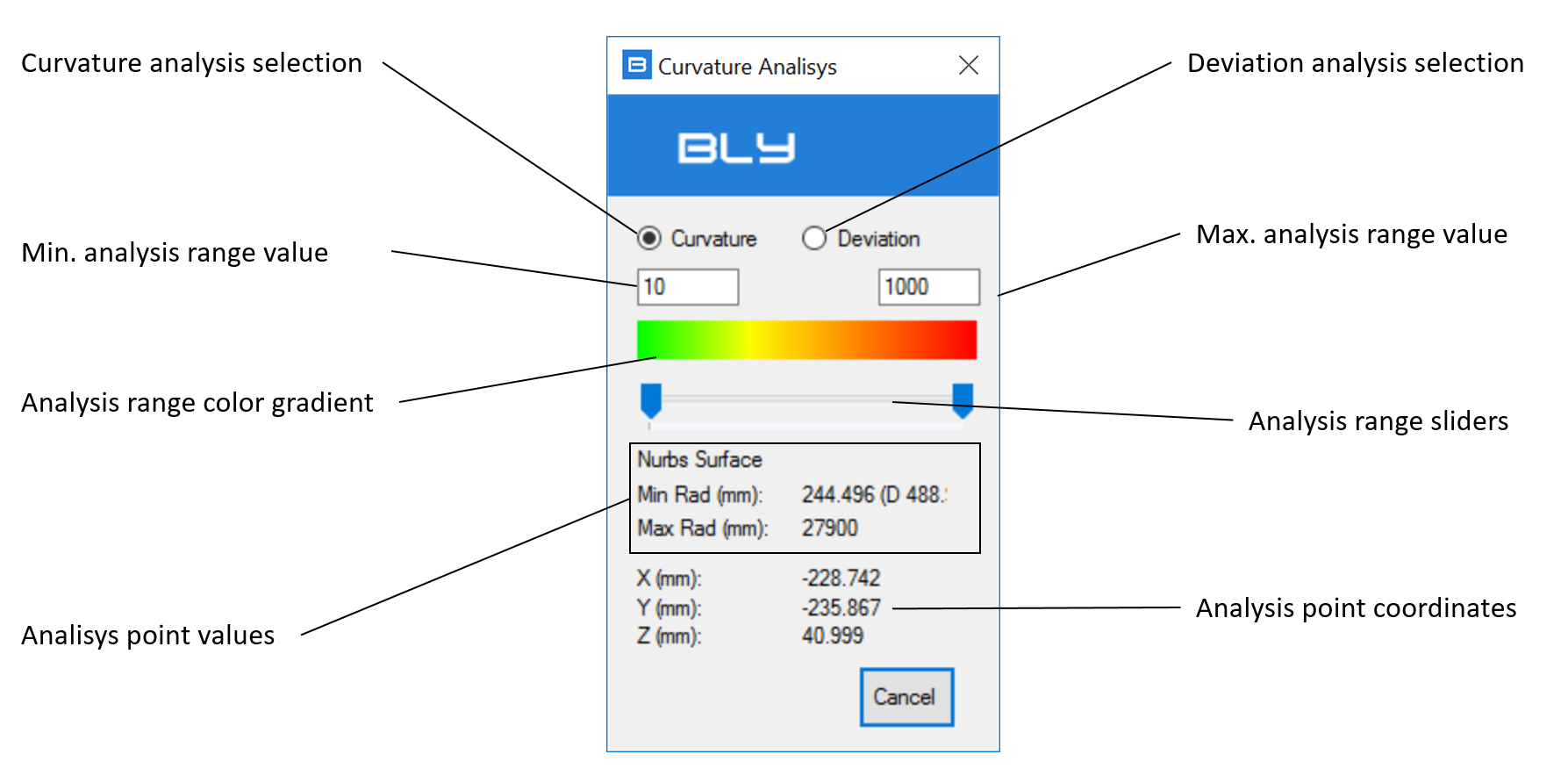
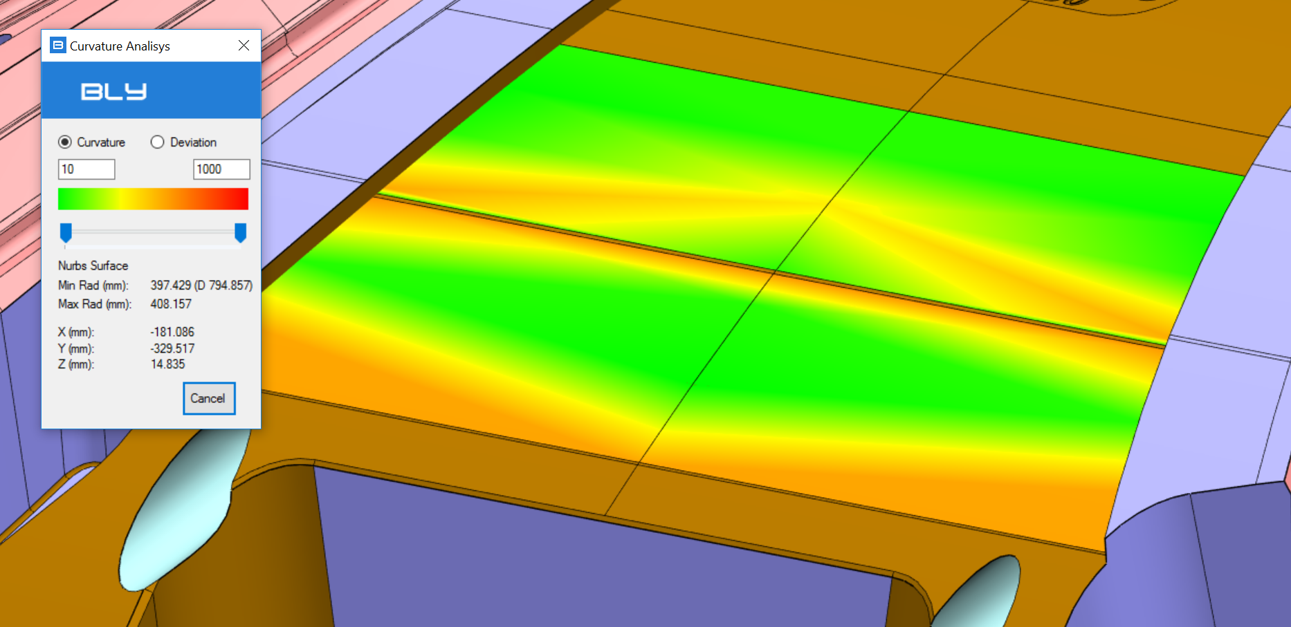
The measurement of the curvature is active selecting the appropriate radio button (see picture).
It measures and graphically represents the radius of curvature of surface(s) selected. Range of color gradient shown can be limited either typing values in the fields or moving the sliders
The bottom section of the window reports the minimum and maximum radius in the point overed with the mouse and its coordinates. Face doesn't need to be selected and can be not included in the gradient analysis.
Deviation measurement
Deviation measurement requires to orient the Z+ as you need (i.e. parallel to the direction of mold extraction): once selected, a manipulator showing the axis is displayed.
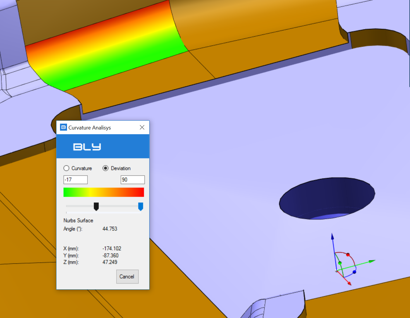
As per the curvature measurement, the window has an upper section for the color gradient and a bottom section for the point overed with the mouse.
Sphere Selection 
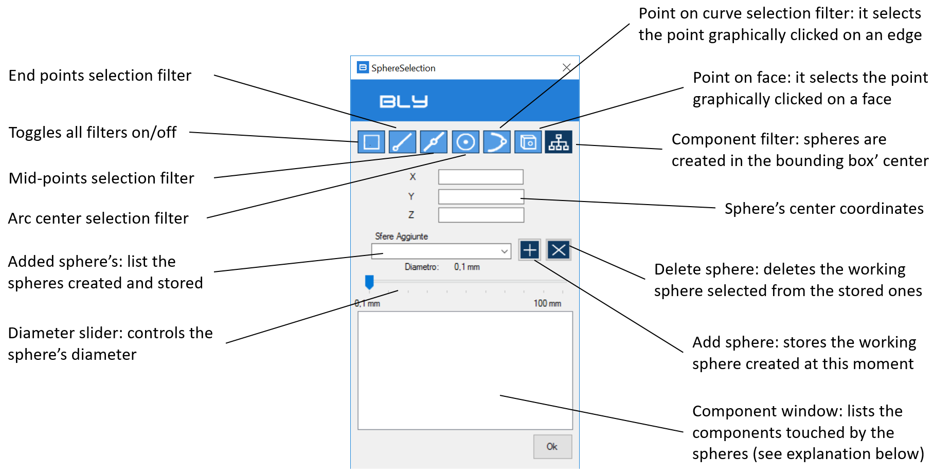
Its selects the components touched by a sphere centered in a selected point.
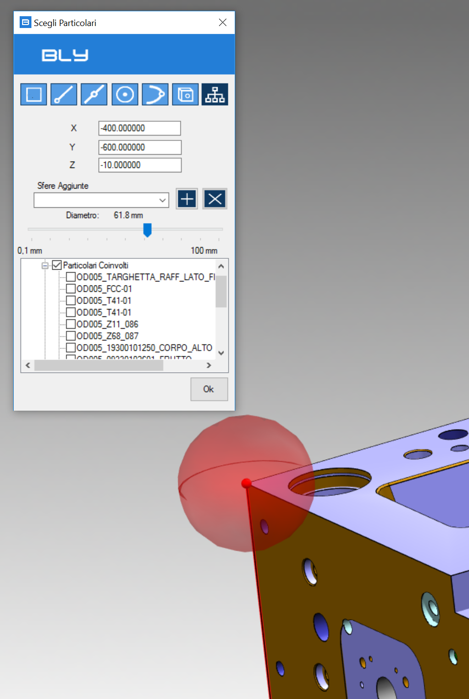
After selecting the point, a sphere is displayed: its diameter can be controlled by the Diameter slider and the components touched are listed in the Component window:
Component window can list, other than components physical touched by the sphere, their mirrored and similar components, if any. After selection, components can be loaded/displayed by thicking them in the list.
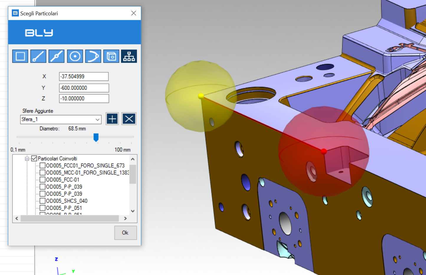
It is possible to save the spheres for further usage and selecting components from multiple locations:
Compare Geometry 
The command creates an assembly to compare two or more components. It is designed to detect geometrical differences between different versions of the same part, sometimes difficult to identify visually.
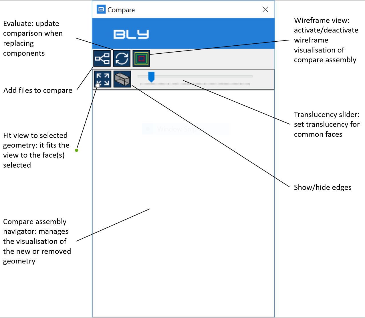
The command can be activated with or without open model(s): once launched, the Compare window will display
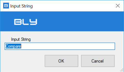
Pressing "Add files to compare", Guideline 4.0 will ask for the name of the compare assembly, which can be freely input be the user
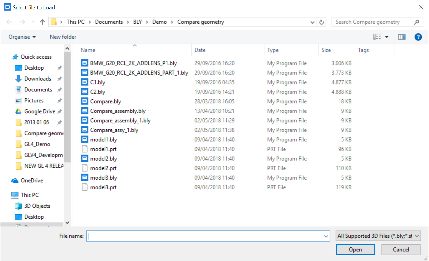
It will be then possible to select the first component from the file system, which can be any supported 3D model (.bly, .stp, .iges or, if Siemens NX is available on the PC, a .prt file)
The compare assembly starts to build
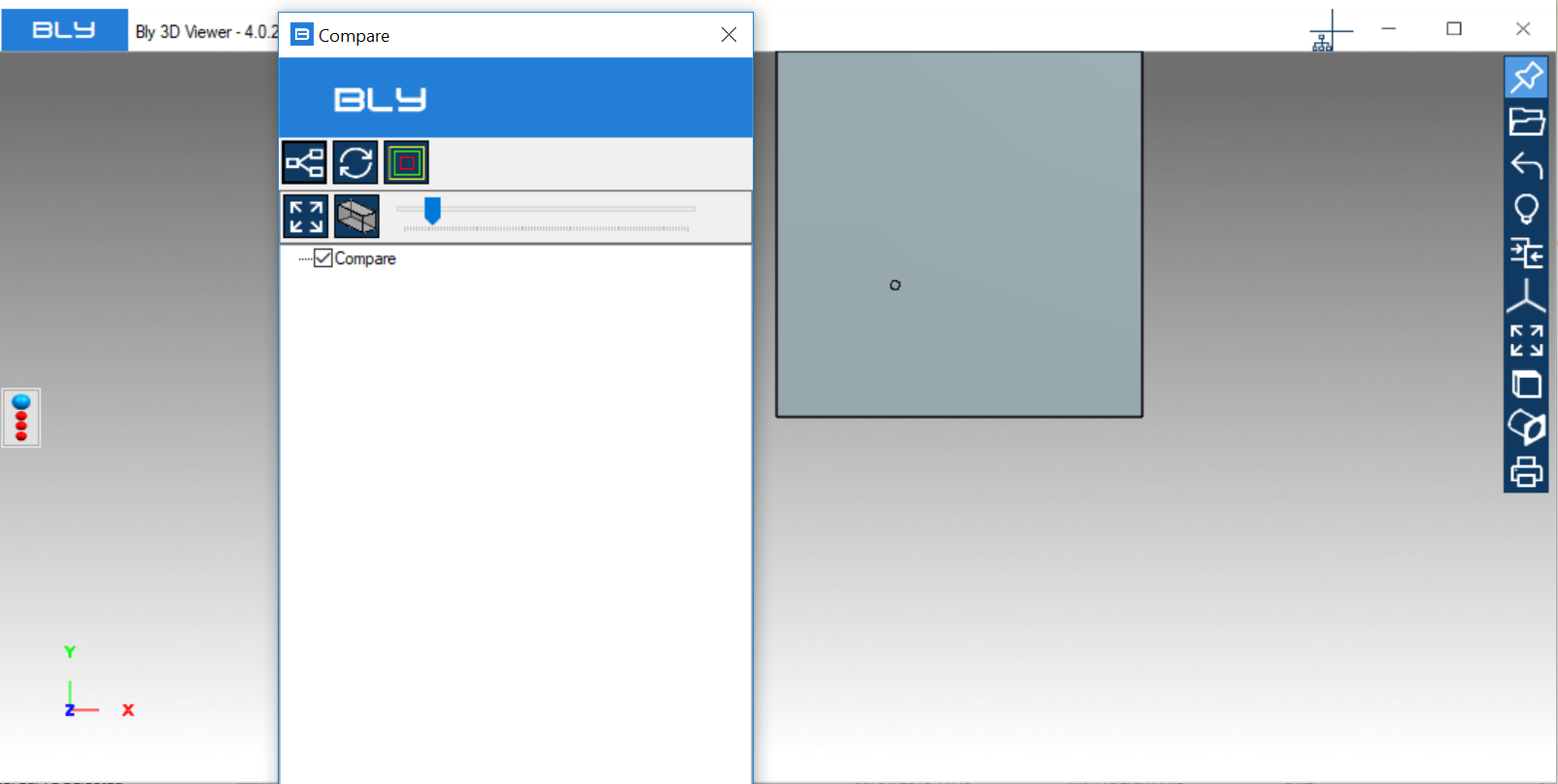
It is then possible to repeat the sequence as many time as the number of the components to be compared: after every addition, compare assembly will update
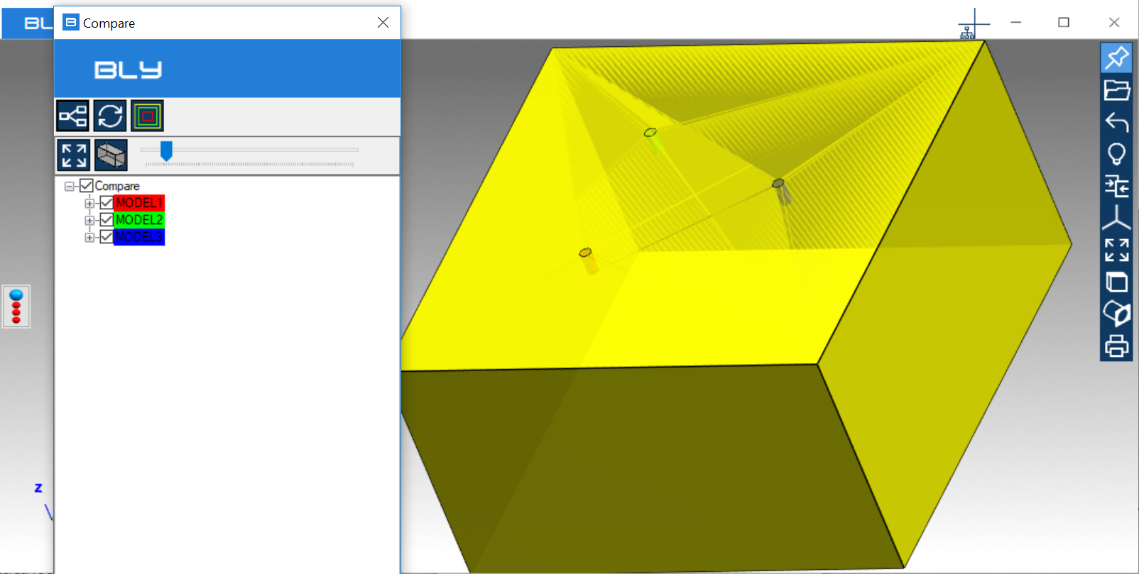
Transparency slider can show or hide the unchanged model, which may be useful to better understand the modifications.
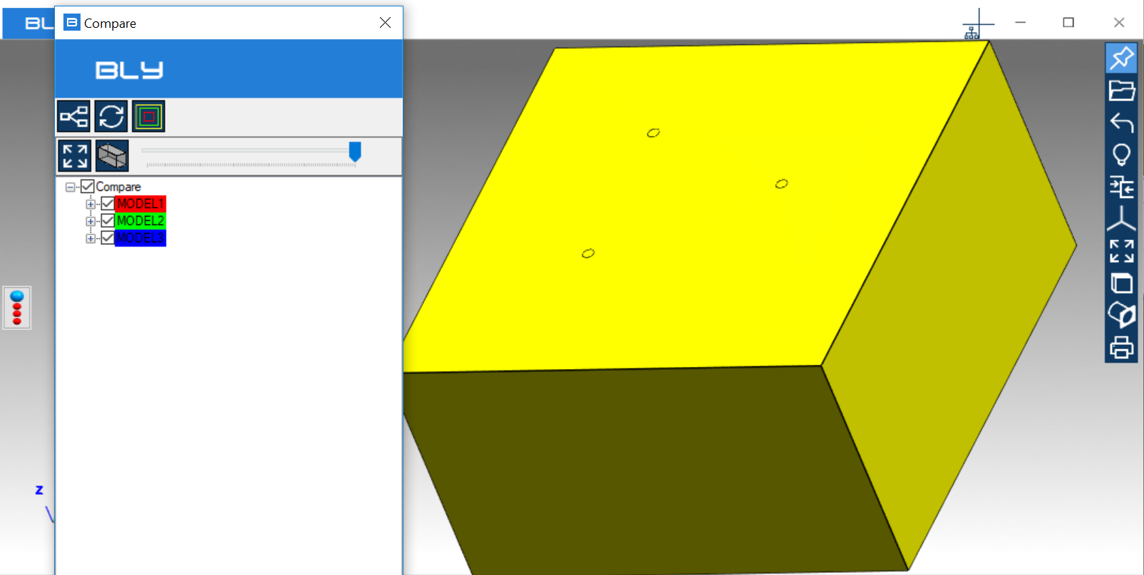
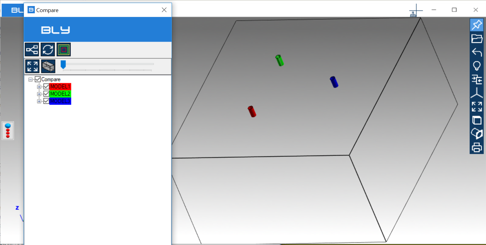
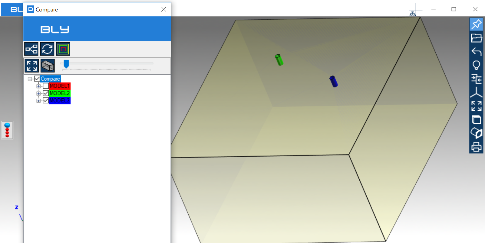
Component(s) can be turned off/on unthicking/thicking them on the Compare tree
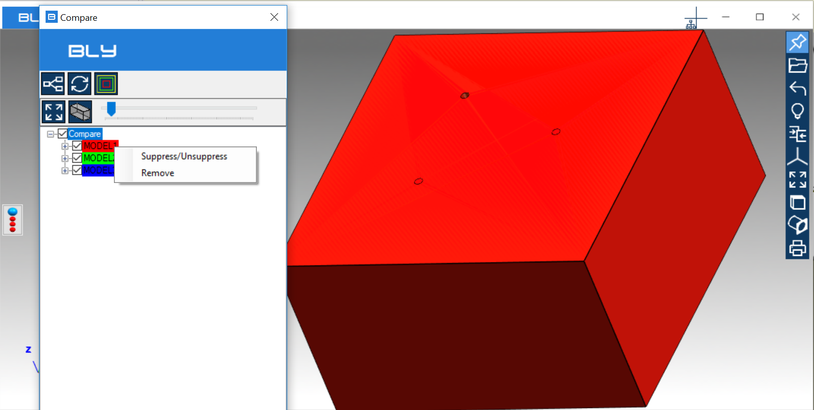
Right-click on the component from Compare tree will allow to Suppress/Unsuppress it: suppression makes a component inactive, but still present in the assembly
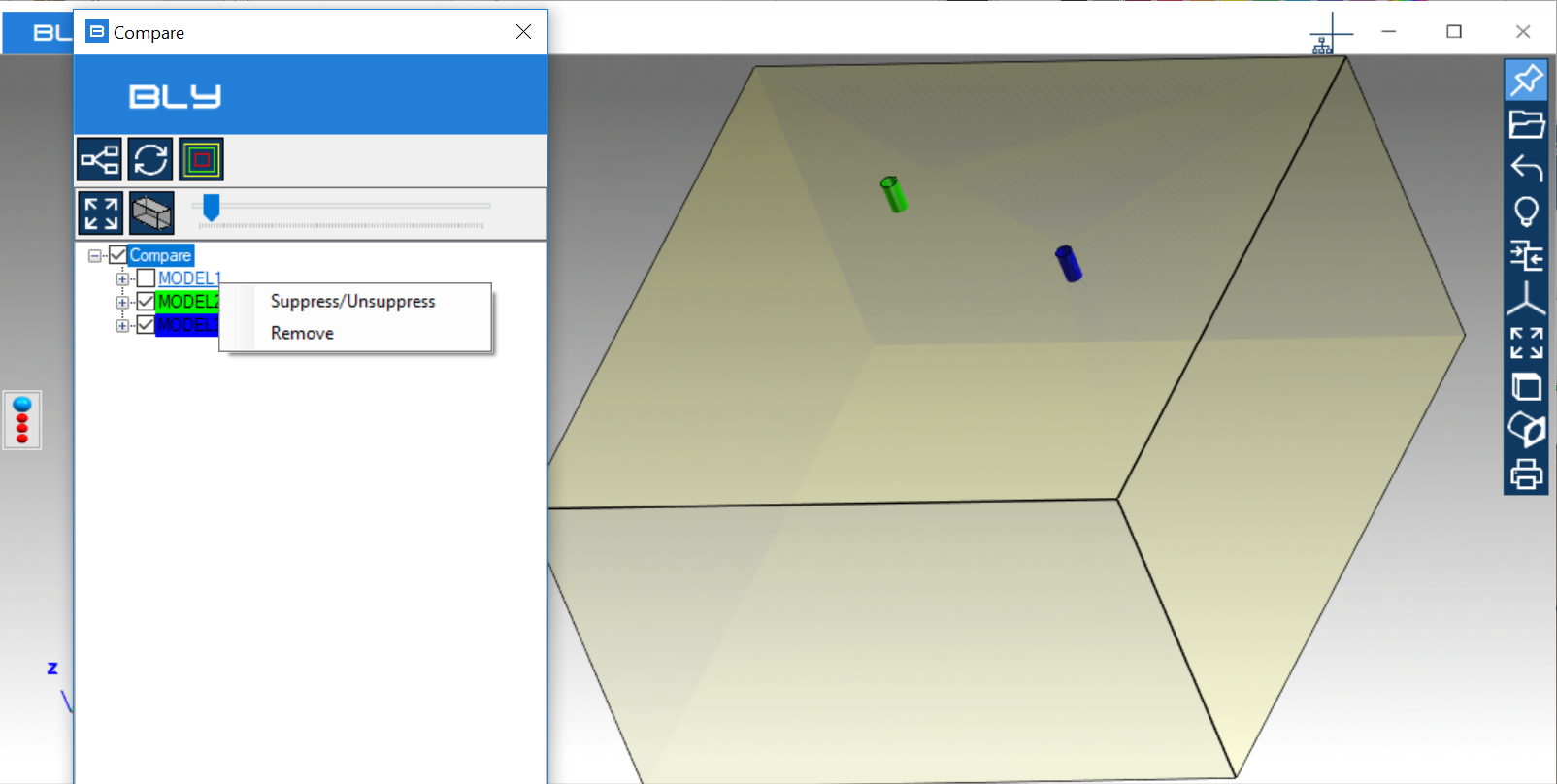
"Remove" will permanently remove the component from the assembly.
After exiting the Compare, the assembly will remain displayed and it will be possible to save it.
Please, see also the related video

